
")
-
Home

-
Products
-
Microscopes and Optical Equipment
-
Light Sources
-
LED Light Sources
-
Collimated LED Light Sources
- Mightex Multi-Wavelength Collimated LED Sources
Mightex Multi-Wavelength Collimated LED Sources

Multiple LED sources can be efficiently combined into a single output beam, and offer major advantages such as long life-time, easily tunable spectrum, high power stability, and ultra-fast switching (on the microseconds level) without using moving mechanical components. Multi-Wavelength Collimated LED Sources find many applications in microscopy, spectroscopy, chemistry, and other physical science application, where light in different wavelengths can be combined into a single collimated output beam that is often further coupled into an optical systems. The highly collimated multi-wavelength output beam is suitable for working with lenses, filters, dichroic, mirrors, and many other optical components, while simultaneously allowing the user to tailor the spectrum to best suit the specific application requirements.
A Multi-Wavelength Collimated LED Source can be constructed by combining the following components (see Assembly Guide for more details):
- Mightex collimated LED sources, and;
- Mightex multi-wavelength beam combiners
Key Features:
- Custom reconfigurable wavelengths and geometry
- 2 to 8 (or more) LED emitters, UV/VIS/NIR
- No moving parts
- Collimated beam, with optional lightguide adapter
- Optional microscope adapters
Assembly Guide
IMPORTANT : (1) LED’s can ONLY be driven by a constant-current source, and NOT a voltage source (e.g. a battery, or a AC/DC power supply etc.); (2) Please always verify LED’s current rating first before applying current to the LED, and please always make sure NOT to apply current that is above the LED’s current rating.
Multi-Wavelength Collimated LED Sources can be constructed by combining the following components:
- Mightex multi-wavelength beam combiners; and
- Mightex collimated LED sources.
As shown in the pictures below, depending on the specific configuration geometry, Multi-Wavelength Collimated LED Sources can be largely categorized into two groups:
- “Straight-through” type, in which each additional LED/wavelength is added to the assembly in series, and hence the first LED/wavelength will have the longest optical path length while the last LED/wavelength will have the shortest; or
- “Equal-path” type, in which all LEDs/wavelengths have equal optical path length at the output.
Below is a step-by-step guide on how to construct a multi-wavelength collimated LED source:
Step-1: Select your desired collimated LED sources (up to 8 or more LED’s) based on wavelengths and output powers, according to the specific requirements for your application. Currently, only 22mm-diameter collimated LEDs can be DIRECTLY combined using Mightex multi-wavelength beam combiners, while 11mm-diameter collimated LEDs can be attached to a beam combiner using an adapter and then combined.
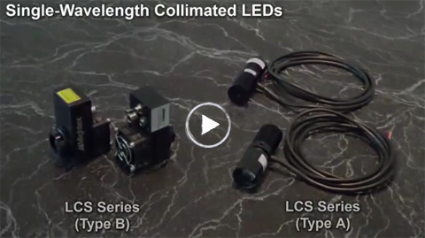
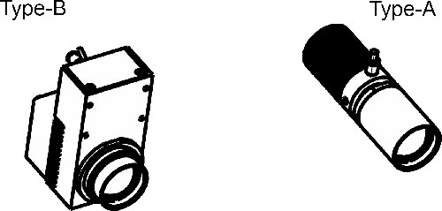
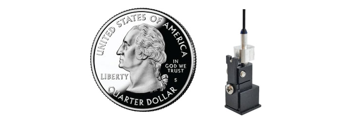
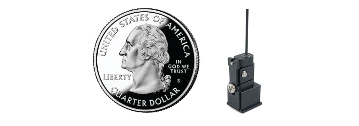
Low-power collimated LED’s (e.g. 5W or below) have a Type-A package, while high-power collimated LED’s (e.g. 7W or above) have a Type-B package (with a cooling fan), as shown below.
Step-2: Rank the selected collimated LED’s by their wavelengths (from long to short). For example, a customer may choose the following four (4) LED’s for his specific application:
1. LED#1, 740nm, 1W, Type-A;
2. LED#2, 590nm, 10W, Type-B;
3. LED#3, 530nm, 15W, Type-B; and
4. LED#4, 470nm, 5W, Type-A.
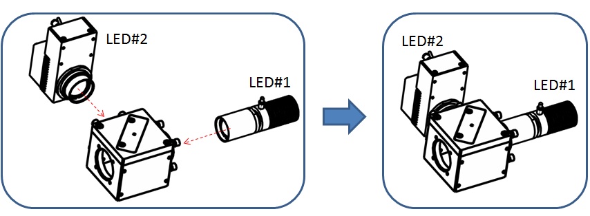
Step-3: Combine LED#1 and LED#2 (i.e. the two LED’s with the longest wavelengths), by selecting the appropriate beam combiner. In this specific example, LCS-BC25-0660 (or LCS-BC25-0685) can be used to combine LED#1 (740nm) and LED#2 (590nm). Result as shown below.
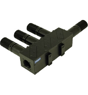
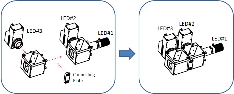
Step-4: Add LED#3 to the sub-assembly, by selecting a 2nd beam combiner. A connecting plate (P/N: ACC-BC25-CP-01/02/03) is used to hold the two beam combiners together. In the specific case discussed here, LED#3 (530nm) can be added to the sub-assembly using a beam combiner LCS-BC25-0560. Result as shown below.
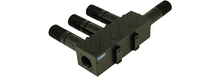
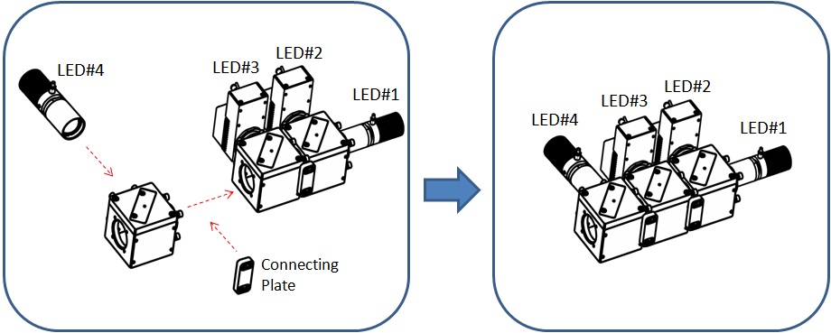
Step-5: Add LED#4 to the sub-assembly, by selecting a 3rd beam combiner. A 2nd connecting plate (P/N: ACC-BC25-CP-01) is used to attach the beam combiner (along with LED#4) to the sub-assembly. In the specific case discussed here, LED#4 (470nm) can be added to the sub-assembly using a beam combiner LCS-BC25-0505. Result as shown below.
Now, all four (4) LED’s have been successfully combined together to form a combined collimated output beam. The following step is OPTIONAL, and it only applies if one would like to (a) further connect the multi-wavelength collimated LED to a microscope; or (b) further couple the combined LED beam into a lightguide.
Step-6 (optional):
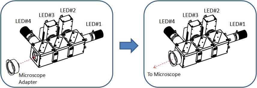
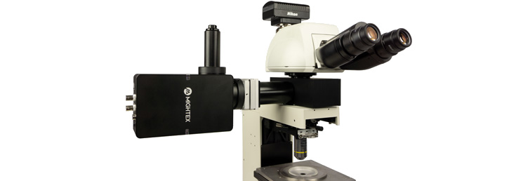
(a) The multi-wavelength collimated LED can be attached to a microscope using a microscope adapter. Result as shown below.
or
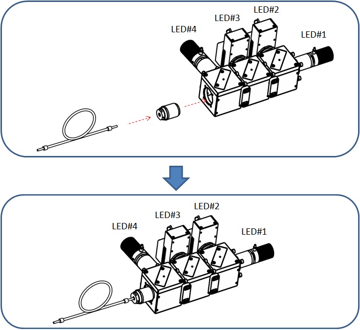
(b) A lightguide adapter can be added to couple the combined collimated LED beam into a lightguide.
Process complete.
(II) – “Equal-Path” Type
Step-1: Select your desired collimated LED sources (up to 8 or more LED’s) based on wavelengths and output powers, according to the specific requirements for your application. Currently, only 22mm-diameter collimated LEDs can be DIRECTLY combined using Mightex multi-wavelength beam combiners, while 11mm-diameter collimated LEDs can be attached to a beam combiner using an adapter and then combined.
Low-power collimated LED’s (e.g. 5W or below) have a Type-A package, while high-power collimated LED’s (e.g. 7W or above) have a Type-B package (with a cooling fan), as shown below.
Step-2: Rank the selected collimated LED’s by their wavelengths (from long to short). For example, a customer may choose the following four (4) LED’s for his specific application:
1.LED#1, 740nm, 1W, Type-A;
2.LED#2, 590nm, 10W, Type-B;
3.LED#3, 530nm, 15W, Type-B; and
4.LED#4, 470nm, 5W, Type-A.
Now, one may put LED#1 and #2 into one group (“Group-1”), and LED#3 and #4 into the other group (“Group-2”).
Step-3: Combine Group-1 (i.e. LED#1 and LED#2, the two LED’s with the longest wavelengths), by selecting the appropriate beam combiner. In this specific example, LCS-BC25-0660 (or LCS-BC25-0685) can be used to combine LED#1 (740nm) and LED#2 (590nm). Result as shown below:
Similarly, Combine Group-2 (i.e. LED#3 and LED#3, the two LED’s with the shortest wavelengths), by selecting the appropriate beam combiner. In this specific example, LCS-BC25-0515 (or LCS-BC25-0495) can be used to combine LED#3 (530nm) and LED#4 (470nm).
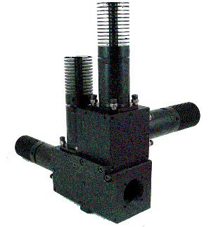
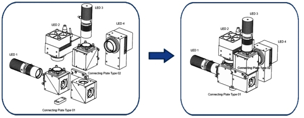
Step-4. Choose a 3rd beam combiner. (e.g. LCS-BC25-0550, and combine Group-1 and Group-2 assemblies into one large assembly, as below:
Now, all four (4) LED’s have been successfully combined together to form a combined collimated output beam. The following step is OPTIONAL, and it only applies if one would like to further connect the multi-wavelength collimated LED to a microscope.
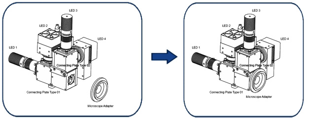
Step-5 (optional): The multi-wavelength collimated LED can be attached to a microscope using a microscope adapter.
Process complete.
Also See:

Related Products:

-
Home
-
Products
-
Microscopes and Optical Equipment
-
Light Sources
-
LED Light Sources
-
Collimated LED Light Sources
- Mightex Multi-Wavelength Collimated LED Sources