
")
-
Home

-
Products
-
-
-
Manufacturers and Suppliers
-
Digitimer
- Digitimer D360
Digitimer D360

 Digitimer D360
Typical Applications might include:
Electroencephalography (EEG) Evoked Potential (EP) Electromyography (EMG)
Computer controlled 8-channel patient-isolated biological amplifier and analogue filter system, meeting all the requirements of the Medical Device Directive. The system comprises a main amplifier unit, a remote active head-box and dedicated Windows (9x, NT, XP) compatible control software.
Multiple D360 systems can be connected to a single computer to allow multiples of 8 channels to be controlled through a single software interface.
Features
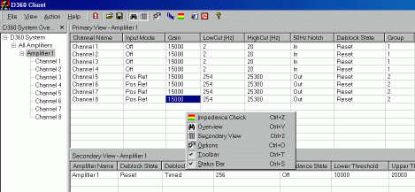
- Individual or grouped control of the gain and filtering characteristics of amplifier channels
- Impedance checking feature allows tri-colour LEDs to indicate problems with any electrodes
- Notch filter (factory set to 50Hz or 60Hz).
- Large range of low-cut and high-cut filter settings.
- Overall gain of x100 to x2,000,000 with outputs at the front (BNC) or rear (D-type) of the main unit
- Software control of amplifier settings
Specifications
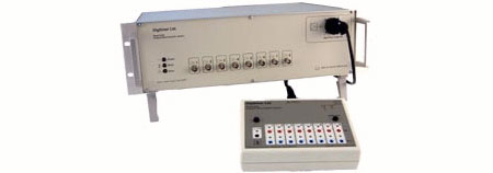
Pre-Amplifier Headstage, Patient Connection Unit
The differential preamplifier is a small A5 sized box containing touch-proof connectors for the patient electrodes with tri-colour LED indication of electrode impedance, when requested. Any combination of channels may be selected to use a Common Reference electrode. Circuitry is included to allow a system check to be performed automatically.
Input impedance of each channel is 100MOhm. On/off control of individual channels. The electronic inputs of individual channels can be grounded reducing cross-talk noise when recording from less channels. This also disconnects the patient from the electronics.
Control enabling the +ve [ref] or -ve [act] input of each channel to be connected to a common Reference input. A channel function test can be performed by grounding the input and performing an impedance check - thereby producing a known output.
The head-box is connected to the main unit via a light weight cable with a plug at the main unit end. Impedance Checking of individual inputs. For each input an LED is situated next to the socket. Pressing the Impedance Check button causes the LED to show one of three colours indicating the impedance of that electrode. The actual value is also passed to the main system for PC display. The impedance range for each colour is programmable from the PC.
Main Unit
The main system unit is a small case that can be bench or rack mounted. It contains the 8 channels of amplification and filtering as well as the processor control circuitry that makes the interface with the PC.
The output of each channel has a BNC socket located on the front panel for connection to research equipment. These signals are duplicated on a pair of rear panel 9-pin D type connectors for direct linking to multi-channel acquisition hardware.
The functionality of each channel is individually set and the amplifier control is connected to a PC via a low-noise serial interface provided on the rear panel. A second interface connector is fitted to the rear panel so that in a multi-system configuration a daisy chain arrangement will allow commands to further D360s without "T" connectors.
The following functions are available on the system
- 8 Channels of amplification, filter and isolation - all parameters are independent.
- Overall System gain for each channel x100 - x200,000 (10mV/V - 5µV/V). Outputs have a ±10V range.
- Low-cut filter settings are variable between 0.1Hz and 200Hz for -3dB and are second order.
- Notch filter - factory set at 50 or 60Hz. User has "in" or "out" control.
- High-cut filter settings are variable between 10Hz and 20kHz for -3dB and are second order.
The front panel contains a single bi-colour LED which is used to indicate the unit's power supply status. It also has an isolated connector for the headstage as well as 8 BNC sockets for monitoring the output of each channel (these signals are mirrored on the rear panel).
The rear panel contains a mains IEC inlet socket with voltage selection, fuses and mains on/off switch. A pair of 9-way female 'D' connectors for connecting all channels to an acquisition system. Also, two sockets for the serial connection to a PC and further D360 systems along with two amber LEDs indicating the serial interface status.
The case is 3U high 19" rack mountable but with retractable legs for bench top use. [ 483 x 300 x 133 mm (w x d x h) plus handles, connectors and feet ]. Mains operating voltage between 90-250V (selectable) and 50-60Hz.
Software
The software provided runs on an IBM PC compatible. The minimum requirements are Windows 9x or NT with Internet Explorer 5.0 or better.
A '.DLL' provides the interface that allows programs such as Visual Basic, Delphi or C/C++ to participate in bi-directional conversations with the D360 hardware.
A Front Panel program (that uses the .DLL) gives a Graphical User Interface (GUI) allowing mouse control of all functions and parameters.
-
Home
-
Products
-
-
-
Manufacturers and Suppliers
-
Digitimer
- Digitimer D360